Fluid-Structure Interaction Simulation of Artificial Heart Valve Considering Open State of Cardiac Cycle
Shahrul Hisyam Marwan1, 2, Mitsugu Todo1, 3
1Department of Molecular and Material Sciences, Interdisciplinary Graduate School of Engineering Sciences, Kyushu University, Fukuoka, Japan.
2School of Mechanical Engineering, College of Engineering, Universiti Teknologi MARA, Terengganu Branch, Bukit Besi Campus, Terengganu, Malaysia.
3Research Institute for Applied Mechanics, Kyushu University, Fukuoka, Japan.
*Corresponding Author: Mitsugu Todo, Associate Professor, Research Institute for Applied Mechanics, Kyushu University, 6-1 Kasuga-koen, Kasuga, Fukuoka 816-8580, Japan
Received: 11 July 2021; Accepted: 20 July 2021; Published: 30 July 2021
Article Information
Citation:
Shahrul Hisyam Marwan, Mitsugu Todo. Fluid-Structure Interaction Simulation of Artificial Heart Valve Considering Open State of Cardiac Cycle. Journal of Biotechnology and Biomedicine 4 (2021): 124-131.
DOI: 10.26502/jbb.2642-91280039
View / Download Pdf Share at FacebookAbstract
The dynamic finite element method with the fluid-structure interaction was used to investigate the deformation behavior of a newly developed artificial heart valve. To reproduce the opening movements of tri-leaflets of the valve during the half cardiac cycle, a time-dependent blood velocity was used as the boundary condition of the fluid domain. The nonslip boundary condition was also chosen for the tri-leaflets to ensure the viscous effect between the blood and the leaflet surfaces, while the free slip boundary condition was chosen for the cylindrical wall to ignore such viscous effect. The valve was assumed to be made from a natural tissue and a linear elastic material was assumed as the material model. The blood was assumed to be incompressible and Newtonian fluid. It was found that the valve was easily open when it came into contact with blood flow, taking only 0.3 seconds to go from fully closed to fully open. The blood flow was also found to be stable with a laminar state and free of turbulence.
Keywords
<p>Artificial heart valve; Fluid-structure interaction; Dynamic finite element method; Solid domain; Fluid domain; Cardiac cycle</p>
Article Details
1. Introduction
Computational simulation techniques have been an important tool for understanding the interaction between artificial aortic heart valves and blood flow. For example, the finite element method (FEM) with the fluid–structure interaction (FSI) has effectively been utilized to simulate the dynamic motion of a heart valve throughout the cardiac cycle [1, 2]. It is however difficult to analyze the hemodynamic performance of blood flow under the strong interaction between the valve and blood flow in the FEM-FSI modeling. To overcome this problem, a precise 3D model of the valve should be created, and the valve's specific properties must be incorporated into the FEM-FSI analysis. In addition, in order to characterize the opening behavior of the valve correctly, the blood flow in the vicinity of the valve must be analyzed. The fluid and structural models have successfully evolved in a couple of simulation systems to accurately represent these interactions, and the accuracy has dramatically been improved.
The aim of this research was to construct a 3D FSI model of a newly developed artificial heart valve with three leaflets taking blood flow into account. To analyze the deformation of the leaflets, the dynamic finite element analysis was used to examine the open response of the valve during the interaction with blood flow by simulating a half cardiac cycle. The hemodynamic behavior of blood flow during the interaction with the valve was also examined in this study.
2. Modeling
2.1 Solid domain
A 3D CAD model of an artificial heart valve was created using a free computer-aided design software Fusion 360 (Autodesk, Inc.), by referring to the substantial details of the geometry provided by Gharaie and Morsi [3]. The external appearances of the 3D model with asymmetric tri-leaflet are shown in Figure 1. The height, diameter and thickness of the 3D model are 8.5, 25.0 and 0.5 mm, respectively [3]. The finite element meshes were created after the 3D model was exported to the finite element code LS-DYNA (Liverware Software, Livermore, CA). The 3D aortic valve was modelled with 17961 tetrahedral solid elements and 6302 nodes as shown in Figure 2. The valve was assumed to be made of a biological tissue used in standard bio-prosthetic heart valves. The density, Young’s modulus, and the Poisson’s ratio were then set to be 1,100 kg/m3 [4–6], 1.0 MPa [4, 7], and 0.3 [4, 8], respectively.

Figure 1: External appearances of artificial heart valve with asymmetric tri-leaflet.
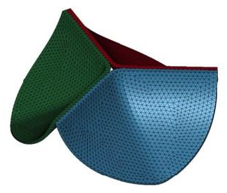
Figure 2: Finite element model of artificial heart valve.
2.2 Fluid domain
The fluid was assumed to be contained in a pipe-like shell structure surrounding the asymmetry tri-leaflets aortic valve model. A 3D CAD model of the fluid domain was created using the 3D-CAD Fusion 360. The length and diameter of the shell structure were 40.0 and 23.5 mm, respectively. The 3D pipe-like shell model with the tri-leaflet valve model are shown in Figure 3. The geometrical data were transferred to LS-DYNA and the finite element meshes were constructed. The fluid domain was discretized with tetrahedral elements, and the pipe-like shell was modelled with 36472 surface elements and 18238 surface nodes, as shown in Figure 4. The fluid was assumed to be incompressible and Newtonian [9], with a constant dynamic viscosity of 0.004 kg/m-s [3, 10] and a density of 1060 kg/m3 [11, 12]
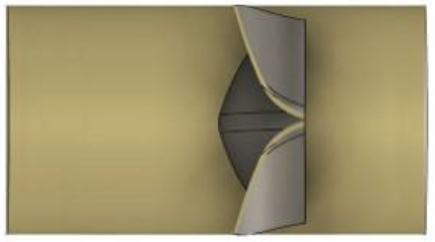
Figure 3: 3D model of pipe-like shell with a tri-leaflet valve.
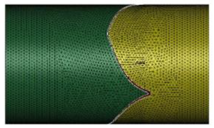
Figure 4: Finite element meshes of fluid domain.
2.3 Boundary conditions
All nodes along the side edges of the asymmetry leaflets were fixed in all directions as the geometrical boundary condition. The fluid domain had two boundaries, namely, inlet and outlet, as shown in Figure 5. The prescribed velocity boundary condition was set on the inlet part to simulate clinically relevant blood flow, while the prescribed pressure boundary condition was set on the outlet with a value of zero to express a continuous flow. An acceleration of 110 mm/s2 was given to the flow to simulate the blood flowing through the aortic valve in our cardiovascular system, starting zero velocity at t = 0 s, and a uniform fluid stream entered the inlet from the left. To express a viscous effect of blood, the nonslip boundary condition was set on the surfaces of the tri-leaflets to ensure the viscous effect between the blood and the leaflets surface, while the free slip boundary condition was given to the cylindrical wall to ignore the viscous effect between the blood and the cylindrical wall.
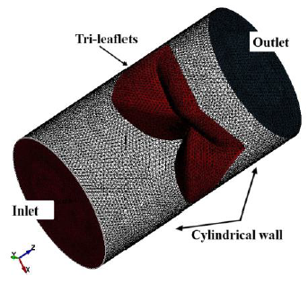
Figure 5: Boundaries of fluid domain.
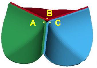
Figure 6: Three points on the tri-leaflets.
3. Results and Discussion
3.1 Dynamic deformation behavior of the artificial heart valve
In this FEM-FSI analysis, the opening behavior of the aortic valve due to the blood flow was successfully observed. The total displacements were measured at the three points on the tri-leaflets shown in Figure 6. The time histories of the displacements are shown in Figure 7 (a). The displacements are almost equivalent, suggesting that the opening behavior of the tri-leaflets are totally symmetric. The displacements at three points are also shown at t=0.4 s in Figure 7 (b). Although the differences are very small, the displacement of the node C was biggest, affecting the hemodynamics of the fluid discussed later.
The deformed images observed from the front view at four different times (points (a)-(d) in Figure.7) are also shown in Figure 8. The valve started to open just before t = 0.1 s without any deformation at point (a). The valve then began to open at t = 0.2 s, resulting in a displacement of 0.26 mm at point (b), and fully opened at t = 0.4 s, resulting in a displacement of 7.60 mm at point (d). It can be seen that the valve demonstrated rapid opening behavior from the point (c) to (d), with the valve's rate of displacement approaching 68 mm/s as shown in Figure 9. This unnatural deformation behavior may be related to the buckling of the linear elastic shell structure
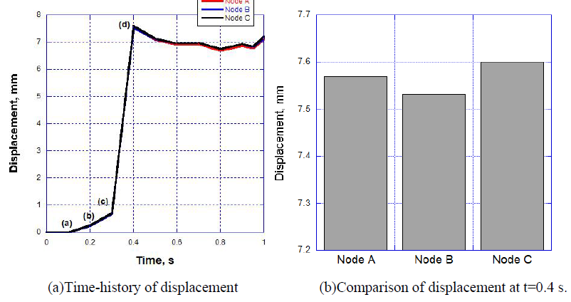
Figure 7: Resultant displacement data at three points.
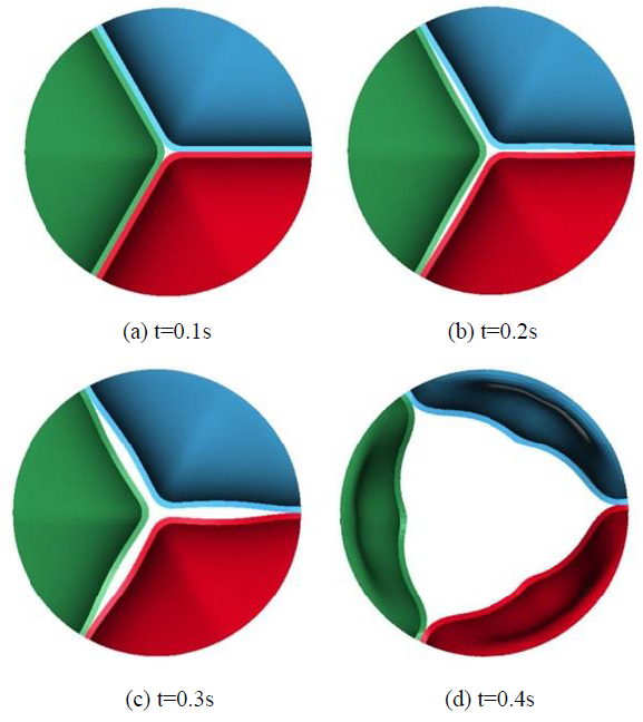
Figure 8: Deformation behaviors of the leaflets.
3.2 Hemodynamic behavior during opening state of artificial heart valve
The hemodynamics of blood flowing through the opening valve was also examined from the results of the FEM-FSI analysis. The fluid velocity vectors are shown in Figure 10 at three different times corresponding to the points (b), (c) and (d) in Figures 8 and 9. The maximum fluid velocity was 362.7 mm/s at t=0.2 s and occurred at the center of the valve, while at t=0.4 s when the valve was fully open, the maximum fluid velocity was 536.5 mm/s and occurred at the slight right-hand location of the center, as shown in Figure 10 (c). This kind of inclination may be related to the unsymmetrical deformation of the leaflets of the valve. As shown in Figure 7 (b), the node C exhibited the largest displacement, indicating that the opening behavior of the leaflet including the node C showed the widest. Actually, the direction of the maximum velocity vector coincided with the direction from the center toward the node C.
The Reynolds numbers evaluated from the maximum velocities at t=0.2 and 0.4 s were Re = 2256 and 3341, respectively, and corresponded to a laminar (Re ≤ 2,300) and transient flow (2,300 < Re < 4000), and no turbulent flow took place in this simulation.
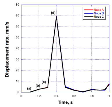
Figure 9: Displacement at the three points shown in Fig.6.

Figure 10: 2D fluid velocity vectors passed through the valve.
4. Conclusions
The FEM-FSI method was successfully used to analyze the dynamic deformation behavior of a newly developed artificial bio-prosthetic heart valve installed in a pipe-like shell structure with blood flow. The opening state of the valve's tri-leaflets was successfully simulated during the half cardiac cycle. It was found that when the valve comes into contact with blood flow, it opens quickly, taking only 0.3 seconds to go from fully closed to fully open state. It was also found that the blood flow was stable and turbulence-free. It was thus concluded that the blood flow is crucial in ensuring that the artificial valve can be opened easily with a laminar flow condition.
References
- AP Yoganathan, KB Chandran, F Sotiropoulos. “Flow in prosthetic heart valves: State-of-the-art and future directions,” Annals of Biomedical Engineering 33 (2005): 1689-1694.
- JH Lee, AD Rygg, EM Kolahdouz, et al. “Fluid–Structure Interaction Models of Bioprosthetic Heart Valve Dynamics in an Experimental Pulse Duplicator,” Annals of Biomedical Engineering 48 (2020): 1475-1490.
- SH Gharaie, Y Morsi. “A novel design of a polymeric aortic valve,” International Journal of Artificial Organs 38 (2015): 259-270.
- R Gnyaneshwar, RK Kumar. “Original article: cardiovascular Dynamic analysis of the aortic valve using a finite” 73 (2002): 3-6.
- M Thubrikar, “The aortic valve,” CRC Press, Boca Raton,Florida (1990): 11-20.
- M Abbasi, MS Barakat, K Vahidkhah, et al. “Characterization of three-dimensional anisotropic heart valve tissue mechanical properties using inverse finite element analysis,” Journal of the Mechanical Behavior of Biomedical Materials 62 (2016): 33-44.
- H Kim, J Lu, MS Sacks et al. “Dynamic simulation pericardial bioprosthetic heart valve function,” Journal of Biomechanical Engineering 128 (2006): 717-724.
- AN Smuts, DC Blaine, C Scheffer, et al. “Application of finite element analysis to the design of tissue leaflets for a percutaneous aortic valve,” Journal of the Mechanical Behavior of Biomedical Materials 4 (2011): 85-98.
- A Vazifehdoostsaleh, M Darjani, A. Bahmani. “Engineering Solid Mechanics” 8 (2020): 271-284.
- CJ Cengel YA, Fluid Mechamics: Fundamentals and Application, Forth Edit (2018).
- CJ Carmody, G Burriesci, IC Howard, et al. “An approach to the simulation of fluid-structure interaction in the aortic valve,” Journal of Biomechanics 39 (2006): 158-169.
- I Borazjani. “Fluid-structure interaction, immersed boundary-finite element method simulations of bio-prosthetic heart valves,” Computer Methods in Applied Mechanics and Engineering 257 (2013): 103-116.


 Impact Factor: * 5.3
 Acceptance Rate: 75.63%
  Time to first decision: 10.4 days
  Time from article received to acceptance: 2-3 weeks